
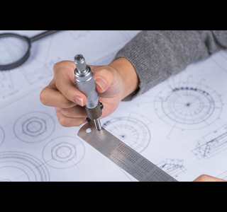
Creating a well-prepared CAD drawing is one of the most important steps in achieving a successful manufacturing project. Even the most advanced machining equipment relies on accurate design data to produce parts that meet exact specifications. A clear and detailed drawing minimizes errors, speeds up production, reduces costs, and ensures that the finished component matches your expectations.
Whether you are designing a simple bracket or a complex industrial component, understanding how to prepare a machining-ready CAD file can make the entire production process smoother. This guide walks you through each step to help you create drawings that are easy for manufacturers to interpret and machine accurately.
Why a Proper CAD Drawing Matters?
A CAD drawing acts as the blueprint for manufacturing. It communicates every important detail about the component, including its size, shape, material, tolerances, and finishing requirements. An incomplete or inaccurate drawing can lead to:
- Production delays
- Dimensional inaccuracies
- Increased manufacturing costs
- Material waste
- Multiple design revisions
A well-prepared drawing, on the other hand, enables engineers and machinists to manufacture the part efficiently while maintaining consistent quality.
Key Steps to Prepare a CNC Machining Drawing (CAD File)
Step 1: Create an Accurate 3D Model
The process begins by designing a precise 3D model using professional CAD software. Popular programs include SolidWorks, Autodesk Inventor, Fusion 360, CATIA, and Siemens NX. The 3D model should represent the final component exactly as it is intended to be manufactured. Avoid leaving unfinished sketches or unnecessary construction geometry within the file. Before moving forward, double-check that:
- All dimensions are correct.
- Features are fully defined.
- There are no overlapping surfaces.
- The model is free from geometry errors.
A clean model reduces programming time and improves machining accuracy.
Step 2: Include Complete Dimensions
Every critical feature should have clearly defined dimensions. These typically include:
- Overall length, width, and height
- Hole diameters
- Hole depths
- Slot dimensions
- Pocket sizes
- Wall thickness
- Corner radii
- Chamfers
Avoid duplicate or conflicting dimensions, as they may confuse the manufacturing team. The goal is to provide enough information so that no assumptions need to be made during production.
Step 3: Specify Manufacturing Tolerances
No manufactured part can be perfectly exact, which is why tolerances are essential. Tolerances define the acceptable variation in a dimension while ensuring the part functions correctly. For example, components that fit together may require tighter tolerances than cosmetic surfaces. Only apply tight tolerances where necessary because excessive precision often increases machining time and manufacturing costs.
Step 4: Clearly Identify Materials
Material selection directly affects machining methods, cutting speeds, tooling, and production costs. Your drawing should clearly specify the required material, such as:
- Aluminum
- Mild steel
- Stainless steel
- Brass
- Copper
- Engineering plastics
- Titanium
Including the material grade helps manufacturers select the correct machining strategy.
Step 5: Add Surface Finish Requirements
Not every surface requires the same level of finish. If certain areas require polishing, grinding, anodizing, coating, or a specific roughness value, indicate these clearly on the drawing. Typical surface finish requirements may include:
- Smooth cosmetic finish
- Machined finish
- Bead blasting
- Powder coating
- Anodizing
- Painting
Providing these details helps avoid additional revisions after production.
Step 6: Identify Threads and Hole Specifications
Threaded holes require complete information. Specify:
- Thread size
- Thread type
- Thread depth
- Number of threaded holes
- Hole diameter
- Counterbore or countersink details if applicable
Incomplete thread information often leads to manufacturing delays or incorrect machining.
Step 7: Include GD&T Where Necessary
Geometric Dimensioning and Tolerancing (GD&T) helps define how features relate to one another beyond basic dimensions. GD&T is particularly useful for:
- Flatness
- Parallelism
- Perpendicularity
- Position
- Concentricity
- Runout
Although not every project requires GD&T, it is extremely valuable for precision components that must assemble accurately.
Step 8: Simplify the Design for Manufacturing
A design may look perfect on a computer but still be difficult or expensive to machine. Consider simplifying features by:
- Avoiding unnecessarily deep pockets
- Reducing extremely thin walls
- Using standard drill sizes
- Minimizing sharp internal corners
- Designing features accessible by cutting tools
Designing with manufacturability in mind reduces machining complexity and production costs.
Step 9: Export the Correct File Format
Different manufacturing systems use different file formats. The most commonly accepted formats include:
- STEP (.stp)
- IGES (.igs)
- Parasolid (.x_t)
- DWG
- DXF
- PDF for drawings
A STEP file is often preferred because it preserves accurate 3D geometry across different CAD software platforms.
Step 10: Review the Entire Drawing
Before sending your files for manufacturing, perform a final quality check. Review:
Dimensions
- Tolerances
- Material specifications
- Surface finish notes
- Hole details
- Revision numbers
- Drawing scale
- Part name and identification
A careful review helps catch small mistakes before they become expensive manufacturing problems.
Common Mistakes to Avoid
Even experienced designers occasionally make errors that slow production. Some common mistakes include:
- Missing dimensions – Leaving out important measurements can lead to incorrect machining and parts that do not fit as intended.
- Incorrect tolerances – Using unrealistic or inaccurate tolerances can increase production costs or result in parts that fail to meet functional requirements.
- Undefined material specifications – Failing to specify the material or grade may cause the wrong material to be used during manufacturing.
- Overcomplicated geometry – Designing unnecessary complex features can make the part more difficult and expensive to machine.
- Missing thread information – Omitting thread size, type, or depth can result in improperly machined threaded holes.
- Conflicting notes – Contradictory instructions or dimensions can confuse machinists and lead to production errors.
- Incorrect file formats – Submitting unsupported or incompatible CAD files may delay the manufacturing process.
- Failure to indicate surface finishes – Not specifying required surface finishes can result in parts that do not meet appearance or performance expectations.
Avoiding these issues saves time for both the designer and the manufacturer.
Working with an Experienced Manufacturing Partner
Preparing a high-quality CAD file is only one part of the manufacturing process. An experienced machining partner can review your design, identify potential production challenges, and recommend improvements before machining begins.
Professional engineering teams often provide Design for Manufacturability (DFM) feedback, helping optimize parts for better performance, reduced production costs, and faster turnaround times. This collaborative approach minimizes revisions and ensures that the finished component meets both functional and quality expectations. Businesses seeking reliable CNC machining services UAE benefit from working with manufacturers who combine advanced equipment with experienced engineering support throughout the production process.
Preparing a machining-ready CAD drawing is about more than simply creating a digital model. A complete drawing should clearly communicate every manufacturing requirement, from dimensions and tolerances to materials and finishing details. Taking the time to organize this information correctly helps reduce production errors, improve efficiency, and achieve higher-quality results.
Whether you are producing prototypes or large production batches, following these best practices will help ensure your CNC machining project moves smoothly from design to finished part while delivering the precision and consistency expected in modern manufacturing.